One-stop solution for Sheet Metal Fabrication & CNC Machining - Bergek CNC
Language
One-stop solution for Sheet Metal Fabrication & CNC Machining - Bergek CNC
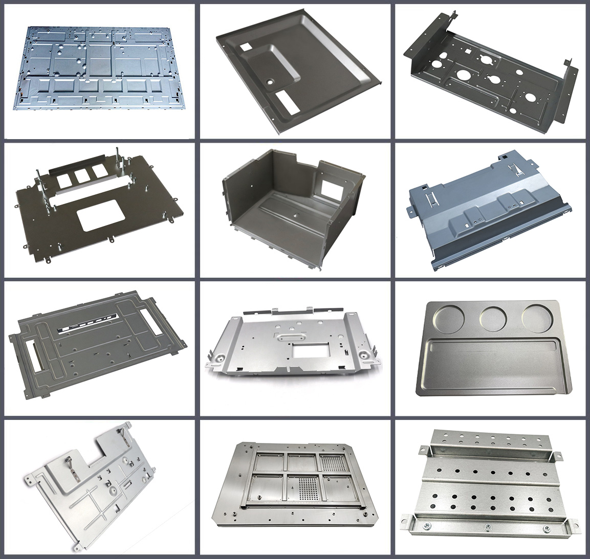
This article describes design guidelines for sheet metal parts, including bends, countersunk holes, hems, dimples, embossing, extruded holes, gussets, hems, holes/slots, lances/louvers, notches/embossing, welding, and plating. Key recommendations include minimum bend radius and flange length, distance between features, maximum depth or width of features, and tooling and manufacturability considerations.
Sheet metal fabrication is a process that allows us to form different parts from a metal sheet using processes like cutting, stamping, forming and punching. Although it might sound like a click-and-go process, it involves a certain level of complexity. First, 3-dimensional CAD files are translated into machine code, this code then controls the machine, ensuring accuracy in every step.
That's why it's important to follow certain sheet metal design guidelines during the design process. These guidelines include important design considerations to help with better machinability, increase overall finishing, and optimize lead times. In this sheet metal design guide, we will uncover some of the most important considerations to help you optimize your sheet metal design. Let’s get going!
These design guidelines are your go-to source to optimize the metal fabrication process.
To ensure smooth manufacturability, mold parts using dedicated sheet metal features in your CAD design, like base flange, edge flange, convert to sheet metal in SolidWorks. Why is this important? This provides better chances for automatic flattering, sufficient bend allowance, and accurate DFX output for fabrication.
During the design phase, avoid using solid-body models for sheets. They sometimes lack critical forming details.
Don’t forget to include 2D engineering drawings with your 3D sheet metal models. What do these drawings do? They clearly communicate:
Critical dimensions
Tolerances Bend notes
Hole callouts
Material specs
Finishing instructions
These instructions are not always embedded in a 3D file, so it's important that you share these in a separate 2D drawing.
Most sheet metal design services rely on these drawings for accurate setup and inspection.
Bend radius is more important than many people think. Flexibility in bend radius allows the use of standard tooling, which is cost-effective and time-saving. Industry best practice is to keep the inside bend radius equal to the sheet’s thickness (for example, 2mm radius for a 2mm thick sheet).
Pro tip: Always confirm the cooling limitations with your fabricator to avoid custom dies.
Don’t forget to leave sufficient clearance for press brake tooling during bending operations. Design features placed too close to the bends like holes, tabs, or cutouts can make the tooling process a bit tricky.
Pro Tip: Keep design features at least 4 times the sheet thickness away from bends. That is, if the sheet is 2mm thick, these features should be at least 8 mm away from the bends.
This makes sure the accurate bends and avoids any complications during the tooling process.
Bends are critical; they can make or break your entire design. Maintain a certain distance between bends and offset bends to maintain the design integrity. Keep a distance of at least 3-4 times the material’s thickness between the bends.
Offset bends require more care; make sure they have enough clearance to avoid any tooling disaster.
To prevent distortion during punching or laser cutting, maintain a minimum diameter equal to the sheet’s diameter between holes and slots. Why is this important? It reduces stress and improves manufacturability.
Pro Tip: To maintain structure integrity and avoid tearing, keep holes at least 2x material thickness from edges and 3x material thickness from bends.
Dimples and embossments are important for any design as they provide necessary stiffness, ventilation and clearing features without bulking the design. A punch or die is normally used to make dimples and embossments.
The final design must maintain a minimum wall thickness and a distance from holes and bends (typically 3x, or even greater in some cases, the material thickness).
By following these sheet metal design guidelines, engineers and designers can make sure the parts they make are not only structurally sound but also budget-friendly, ready for fabrication and production.
Sheet Metal Manufacturing Technology
The following are six main sheet metal manufacturing technologies:
Bending
Bending mainly refers to bending a specific part of a steel plate to produce the desired curvature or angle. This method is usually completed using a mechanical bending machine or a manual bending tool. It usually takes multiple bends to get the desired shape.
Laser Cutting
Laser cutting is a processing technology that uses a high-energy laser beam to accurately cut metal sheets. The laser beam can be controlled and focused to cut complex shapes and contours.
Stretching
Stretching is a method of stretching a steel plate. This method is often used to make thin plate parts or equipment. In this process, the material needs to be stretched to make it thinner and longer in the length direction. Stretching is usually done using a press and special stretching equipment.
Welding
Welding is a processing method that connects metal plates together through a heat source. Common welding methods include arc welding, laser welding, gas shielded welding, etc., which are used to connect different parts or plates.
Rolling
Rolling is a process that applies force to the metal sheet through rollers to make it pass through the gap between the rollers, thereby changing the shape and size of the sheet. Rolling is often used for thinning, straightening and shape correction of metal sheets.
Stamping
Stamping is a method of forming steel sheets into the desired shape, usually used to produce high-precision parts. This method uses a special stamping die to place the steel sheet on a fixed substrate, and then uses high-pressure gas or mechanical force to press the steel sheet to form it into the desired shape.
Impact of Materials on Sheet Metal Design
Material tolerances are inherent characteristics of sheet metal parts, characterized by inherent variations due to factors such as material properties and manufacturing processes. These tolerances are particularly affected by material thickness, with each thickness category having different tolerance grades.
Material Tolerances - Thickness
Selecting the appropriate sheet thickness is a critical step in sheet metal manufacturing. This choice affects a variety of factors, including the overall strength and weight of the part, as well as overall design features such as minimum bend radius, hole and slot size, and flange length. Ensuring uniform thickness throughout the sheet metal part is critical to ensuring consistent quality and performance.
Material Thickness Guidelines
A common trend in material tolerances is to tend toward negative tolerances. This means that the actual dimensions of the finished part may be slightly smaller than specified in the design. This is a critical factor to consider during design and manufacturing to ensure the functional and structural integrity of the final product.
For a detailed and specific understanding, it is recommended to consult the thickness tolerance table. This table provides comprehensive insight into the expected differences between different materials and thicknesses and is a valuable resource for designers and manufacturers seeking precision and quality in the finished product.
Material Tolerances - Properties
Sheet metal materials can vary in physical properties, such as surface tension, springback, tensile strength, etc., depending on the material and process used to produce them.
When selecting materials, you need to consider the amount of variation allowed by your design and a safety factor. For example, hot-rolled carbon steel generally has greater material variation than cold-rolled carbon steel (although hot-rolled carbon steel also costs more due to secondary operations). For more precise bends, cold-rolled steel is a better choice because it limits the variation between material batches and improves bend consistency.
| Materials | Density (g/cm ³) | Thermal Expansion Coefficient | Modulus (GPa) | Processing Difficulty | Physical Property | Application |
| Aluminum | 2.7 | 23-24 | 70 | Easy to process | Lightweight, good thermal conductivity and conductivity | Aircraft parts, automotive components, electronic equipment casings |
| Stainless Steel | 7.9 | 16-18 | 193 | Moderate | Corrosion resistance, high strength | Kitchenware, ship components, chemical equipment |
| Copper | 8.9 | 16-18 | 120 | Moderate | Good conductivity and corrosion resistance | Electrical parts, pipelines, decorations |
| Titanium | 4.5 | 8-10 | 110-130 | Easy to process | Lightweight, high-strength | Aerospace components, medical devices |
| Brass | 8.4-8.7 | 19-20 | 100-125 | Difficult to process | Good conductivity and corrosion resistance | Music instruments, decorations, pipes |
Tolerances Guideline for Sheet Metal Fabrication
Tolerances are the allowed deviations in a product's dimensions or other characteristics. When designing a sheet metal product, it is important to consider the tolerances that are acceptable for the product's intended use. Some applications may require tighter tolerances, such as those that require a precise fit or alignment.
Sheet Metal Processing General Tolerance Table
| Forming or bending | +/- 0.508 mm (0.020") |
| Bend to hole or feature | +/-0.254 mm (0.010") |
| Diameters with inserts | +/-0.0762 mm (0.003") |
| Angularity | +/- 1° |
| Holes | +/-0.127 mm (0.005") |
| Edge to edge | ±0.127 mm (0.005") |
| Edge to hole | ±0.127 mm (0.005") |
| Hole to hole | ±0.127 mm (0.005") |
| Hole to hardware | ±0.254 mm (0.010") |
| Edge to hardware | ±0.254 mm (0.010") |
| Hardware to hardware | ±0.381 mm (0.015") |
| Bend to hole | ±0.381 mm (0.015") |
| Bend to hardware | ±0.381 mm (0.015") |
| Bend to edge | ±0.254 mm (0.010") |
| Bend to bend | ±0.381 mm (0.015") |
Even with years of experience with sheet metal design, there will be some mistakes. Follow these practical tips to get fabrication-ready designs each time:
Design flanges based on material thickness
Avoid features too close to bends
Use common materials & standards
Radius the sharp corners to prevent cracking
Leave room for tool access in forming
Mistakes are unavoidable, but when you follow these design tips, there is a high chance that you may get away with some of them.
Design is probably the most important phase in any fabrication project. One mistake, and you are in for some serious trouble. However, when you follow the sheet metal design guidelines outlined in this article, you bring the probability of mistakes to near Zero.
Doesn’t matter which sheet metal design software you are using; following the industry best practices will always help. If you are looking for the top sheet metal design service, there is only one name that pops up: BERGEK. With years of experience in the field, BERGEK is sure to be your design and fabrication partner for years to come.
FAQ
How important is material thickness in sheet metal design?
In sheet metal design, it is critical to maintain uniform wall thickness. Sheet metal parts typically range in thickness from 0.9 mm to 20 mm. The guide emphasizes that punches (holes) and other features (such as countersunk holes) must be considered when determining thickness, as some features may require post-processing.
What are the key considerations for bending in sheet metal design?
Bending is a critical process in sheet metal manufacturing. This guide details the importance of factors such as bend radius, bend angle, and springback. The guide recommends that the inside radius of the bend should be at least equal to the material thickness and that a tolerance of +/- 1 degree should be maintained for all bend angles. In addition, the guide discusses the importance of maintaining consistent guides and minimum flange length during the bend process.
Can you explain the role of K-factor in sheet metal design?
K-factor is critical when calculating plan views in sheet metal design. It is related to the material stretch during the bend process. This guide provides a range of K factors (0 – 0.5) and a chart with basic K factor values for different materials and bending methods.
How do tolerances affect sheet metal design?
Tolerances are critical to ensuring the accuracy of sheet metal parts. This guide provides common tolerances for all aspects of sheet metal manufacturing, including forming, bending, and linear dimensions. The guide emphasizes the importance of accuracy to meet design specifications and functional requirements.
Get In Touch With Us!
Bergek CNC is a world-class manufacturing service provider in Shenzhen. We have advanced equipment to provide a full range of customized products to manufacturers around the world, specializing in CNC machining and sheet metal processing.
If you have any question,please contact us.

Copyright © 2026 SHENZHEN BERGEK TECHNOLOGY CO., LTD. - www.bergekcnc.com All Rights Reserved.